Software Implementation
Project Structure
your_project/
├── CMakeLists.txt
└── main/
    ├── CMakeLists.txt
    ├── main.c
    ├── gps_sync.h
    └── gps_sync.c
gps_sync.h - Header File
#pragma once

#include <stdint.h>
#include <time.h>
#include "freertos/FreeRTOS.h"
#include "freertos/semphr.h"

typedef struct {
    int64_t monotonic_us;   // Never jumps backward
    int64_t gps_us;         // GPS UTC time in microseconds
    bool synced;            // true if GPS has valid fix
} gps_timestamp_t;

// Initialize GPS sync system
void gps_sync_init(void);

// Get current timestamp
gps_timestamp_t gps_get_timestamp(void);

// Check if GPS is synced
bool gps_is_synced(void);
gps_sync.c - Implementation
#include "gps_sync.h"
#include "driver/gpio.h"
#include "driver/uart.h"
#include "esp_timer.h"
#include "esp_log.h"
#include <string.h>
#include <time.h>
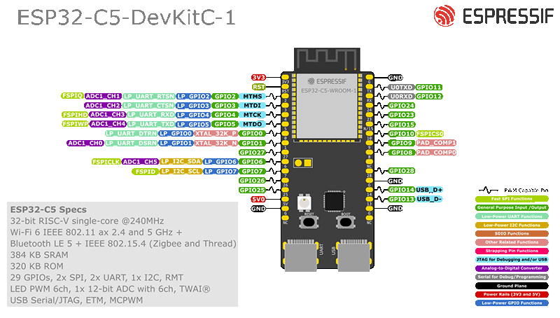
#define GPS_UART_NUM UART_NUM_1
#define GPS_RX_PIN GPIO_NUM_4
#define GPS_TX_PIN GPIO_NUM_5
#define PPS_GPIO GPIO_NUM_1
#define GPS_BAUD_RATE 9600
#define UART_BUF_SIZE 1024
static const char *TAG = "GPS_SYNC";
// GPS sync state
static int64_t monotonic_offset_us = 0;
static volatile int64_t last_pps_monotonic = 0;
static volatile time_t next_pps_gps_second = 0;
static bool gps_has_fix = false;
static SemaphoreHandle_t sync_mutex;
// PPS interrupt - captures exact monotonic time at second boundary
static void IRAM_ATTR pps_isr_handler(void* arg) {
last_pps_monotonic = esp_timer_get_time();
}
// Parse GPS time from NMEA sentence
static bool parse_gprmc(const char* nmea, struct tm* tm_out, bool* valid) {
if (strncmp(nmea, "$GPRMC", 6) != 0 && strncmp(nmea, "$GNRMC", 6) != 0) {
return false;
}
char *p = strchr(nmea, ',');
if (!p) return false;
// Time field
p++;
int hour, min, sec;
if (sscanf(p, "%2d%2d%2d", &hour, &min, &sec) != 3) {
return false;
}
// Status field (A=valid, V=invalid)
p = strchr(p, ',');
if (!p) return false;
p++;
*valid = (*p == 'A');
// Skip to date field (8 commas ahead from time)
for (int i = 0; i < 7; i++) {
p = strchr(p, ',');
if (!p) return false;
p++;
}
// Date field: ddmmyy
int day, month, year;
if (sscanf(p, "%2d%2d%2d", &day, &month, &year) != 3) {
return false;
}
year += (year < 80) ? 2000 : 1900;
tm_out->tm_sec = sec;
tm_out->tm_min = min;
tm_out->tm_hour = hour;
tm_out->tm_mday = day;
tm_out->tm_mon = month - 1;
tm_out->tm_year = year - 1900;
tm_out->tm_isdst = 0;
return true;
}
// GPS processing task
static void gps_task(void* arg) {
char line[128];
int pos = 0;
while (1) {
uint8_t data;
int len = uart_read_bytes(GPS_UART_NUM, &data, 1, 100 / portTICK_PERIOD_MS);
if (len > 0) {
if (data == '\n') {
line[pos] = '\0';
struct tm gps_tm;
bool valid;
if (parse_gprmc(line, &gps_tm, &valid)) {
if (valid) {
time_t gps_time = mktime(&gps_tm);
xSemaphoreTake(sync_mutex, portMAX_DELAY);
next_pps_gps_second = gps_time + 1;
xSemaphoreGive(sync_mutex);
vTaskDelay(pdMS_TO_TICKS(300));
xSemaphoreTake(sync_mutex, portMAX_DELAY);
if (last_pps_monotonic > 0) {
int64_t gps_us = (int64_t)next_pps_gps_second * 1000000LL;
int64_t new_offset = gps_us - last_pps_monotonic;
if (monotonic_offset_us == 0) {
monotonic_offset_us = new_offset;
} else {
// Low-pass filter: 90% old + 10% new
monotonic_offset_us = (monotonic_offset_us * 9 + new_offset) / 10;
}
gps_has_fix = true;
ESP_LOGI(TAG, "GPS sync: %04d-%02d-%02d %02d:%02d:%02d, offset=%lld us",
gps_tm.tm_year + 1900, gps_tm.tm_mon + 1, gps_tm.tm_mday,
gps_tm.tm_hour, gps_tm.tm_min, gps_tm.tm_sec,
monotonic_offset_us);
}
xSemaphoreGive(sync_mutex);
} else {
gps_has_fix = false;
}
}
pos = 0;
} else if (pos < sizeof(line) - 1) {
line[pos++] = data;
}
}
}
}
void gps_sync_init(void) {
ESP_LOGI(TAG, "Initializing GPS sync");
sync_mutex = xSemaphoreCreateMutex();
uart_config_t uart_config = {
.baud_rate = GPS_BAUD_RATE,
.data_bits = UART_DATA_8_BITS,
.parity = UART_PARITY_DISABLE,
.stop_bits = UART_STOP_BITS_1,
.flow_ctrl = UART_HW_FLOWCTRL_DISABLE,
.source_clk = UART_SCLK_DEFAULT,
};
ESP_ERROR_CHECK(uart_driver_install(GPS_UART_NUM, UART_BUF_SIZE, 0, 0, NULL, 0));
ESP_ERROR_CHECK(uart_param_config(GPS_UART_NUM, &uart_config));
ESP_ERROR_CHECK(uart_set_pin(GPS_UART_NUM, GPS_TX_PIN, GPS_RX_PIN,
UART_PIN_NO_CHANGE, UART_PIN_NO_CHANGE));
gpio_config_t io_conf = {
.intr_type = GPIO_INTR_POSEDGE,
.mode = GPIO_MODE_INPUT,
.pin_bit_mask = (1ULL << PPS_GPIO),
.pull_up_en = GPIO_PULLUP_ENABLE,
.pull_down_en = GPIO_PULLDOWN_DISABLE,
};
ESP_ERROR_CHECK(gpio_config(&io_conf));
ESP_ERROR_CHECK(gpio_install_isr_service(0));
ESP_ERROR_CHECK(gpio_isr_handler_add(PPS_GPIO, pps_isr_handler, NULL));
xTaskCreate(gps_task, "gps_task", 4096, NULL, 5, NULL);
ESP_LOGI(TAG, "GPS sync initialized (RX=GPIO%d, PPS=GPIO%d)", GPS_RX_PIN, PPS_GPIO);
}
gps_timestamp_t gps_get_timestamp(void) {
gps_timestamp_t ts;
xSemaphoreTake(sync_mutex, portMAX_DELAY);
ts.monotonic_us = esp_timer_get_time();
ts.gps_us = ts.monotonic_us + monotonic_offset_us;
ts.synced = gps_has_fix;
xSemaphoreGive(sync_mutex);
return ts;
}
bool gps_is_synced(void) {
return gps_has_fix;
}
main.c - Example Usage
#include <stdio.h>
#include "freertos/FreeRTOS.h"
#include "freertos/task.h"
#include "esp_log.h"
#include "gps_sync.h"

static const char *TAG = "MAIN";

void log_collapse_event(float nav_duration_us, int rssi) {
    gps_timestamp_t ts = gps_get_timestamp();

    // CSV format: monotonic_us, gps_us, synced, nav_duration, rssi
    printf("COLLAPSE,%lld,%lld,%d,%.2f,%d\n",
           ts.monotonic_us,
           ts.gps_us,
           ts.synced ? 1 : 0,
           nav_duration_us,
           rssi);
}

void app_main(void) {
    ESP_LOGI(TAG, "Starting GPS sync");

    gps_sync_init();

    ESP_LOGI(TAG, "Waiting for GPS fix...");
    while (!gps_is_synced()) {
        vTaskDelay(pdMS_TO_TICKS(1000));
    }
    ESP_LOGI(TAG, "GPS synced!");

    while (1) {
        gps_timestamp_t ts = gps_get_timestamp();

        ESP_LOGI(TAG, "Time: mono=%lld gps=%lld synced=%d",
                ts.monotonic_us, ts.gps_us, ts.synced);

        // Example: log collapse event
        if (ts.monotonic_us % 10000000 < 100000) {
            log_collapse_event(1234.5, -65);
        }

        vTaskDelay(pdMS_TO_TICKS(1000));
    }
}
CMakeLists.txt
idf_component_register(SRCS "main.c" "gps_sync.c"
                      INCLUDE_DIRS ".")
Integration with iperf2
On Raspberry Pi 5 (iperf2 Server)
Your Pi is already GPS-synced. Run iperf2 with timestamps:
# Server mode with histograms and trip-times
iperf -s --histograms --trip-times -i 0.1

# Or as client testing against a target
iperf -c target_ip --histograms --trip-times -i 0.1
Correlation Analysis
Both systems now share GPS time. Example Python analysis:
import pandas as pd
import matplotlib.pyplot as plt

# Load ESP32 collapse events
esp32_events = pd.read_csv('collapse_events.csv',
                           names=['event', 'mono_us', 'gps_us', 'synced', 'nav_dur', 'rssi'],
                           parse_dates=['gps_us'],
                           date_parser=lambda x: pd.to_datetime(int(x), unit='us'))

# Load iperf2 data
iperf_data = pd.read_csv('iperf_histograms.csv',
                         parse_dates=['timestamp'])

# Merge on GPS timestamp (within 100ms window)
merged = pd.merge_asof(iperf_data.sort_values('timestamp'),
                       esp32_events.sort_values('gps_us'),
                       left_on='timestamp',
                       right_on='gps_us',
                       tolerance=pd.Timedelta('100ms'),
                       direction='nearest')

# Plot latency vs collapse events
fig, ax1 = plt.subplots(figsize=(12, 6))
ax1.plot(merged['timestamp'], merged['latency_ms'], 'b-', label='Latency')
ax1.set_ylabel('Latency (ms)', color='b')

ax2 = ax1.twinx()
collapse_times = merged[merged['event'] == 'COLLAPSE']['timestamp']
ax2.scatter(collapse_times, [1]*len(collapse_times), color='r', marker='x', s=100, label='Collapse')
ax2.set_ylabel('Collapse Events', color='r')

plt.title('WiFi Latency vs Collapse Detection Events')
plt.show()